
The TH700R4 rebuild page.
This is my first stab at rebuilding a slush box, so we'll have to see how it works out. It can't be that bad though,
as I know a couple of more or less retarded people that can do it, so why shouldn't I?
Also, this will not be a complete rebuild, I'm just freshing up things a bit.
You still need a TH700R4 repair manual to do this, despite reading this page!
Let's start with some background and a little history of what I did before I started this page.
First I drained the transmission and put it on my temporary work bench made up just for this purpouse. Oh, after
a good cleaning of the outside tranny case, of course. For cleaning, and for parts cleaning I use E85 which is a
mixture of 85% anhydrous ethanol and 15% gasoline.
First off, a few things that I don't mention much throughout this page:
Some gaskets are different between transmission years. Match up all gaskets!
When assembling the transmission, Change all seals and o-rings.
Keep things clean.
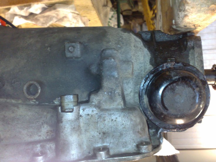
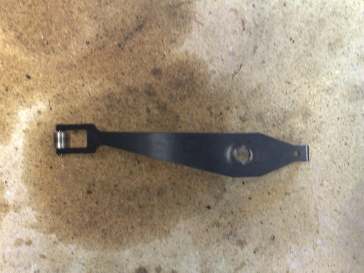
So, first thing after getting it on the surgery table is to take out the servo behind the servo cover. For this you
need a tool to push down the servo cover while you pry off the lock ring. I made my own tool from some scrap I had
in the bin, you may too if you don't prefer to buy the insanely expensive GM special tool...
It looks like this:
Special tool used to depress servo cover to remove it.
Here's a picture of the servo cover and assembly when pulled out of the transmission:

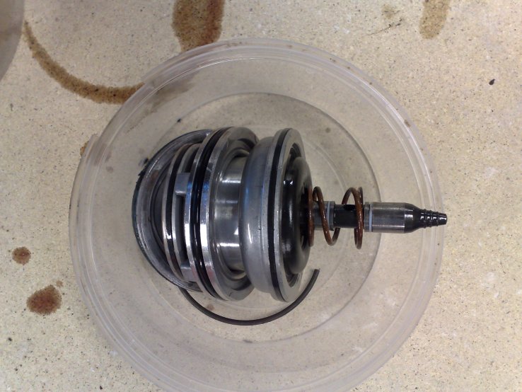
Servo assembly, cover, and lock ring.
Next thing you do is to remove the governor from the transmission case. Tap the governor cover off with a puch or
large screw driver, careful not to distort the cover. Then pull out governor assembly and clean in parts washer.
Now you pull the speedometer gear, just take the bracket off that holds it and the pull it out.
The governor assembly and the spedometer gear looks like this:
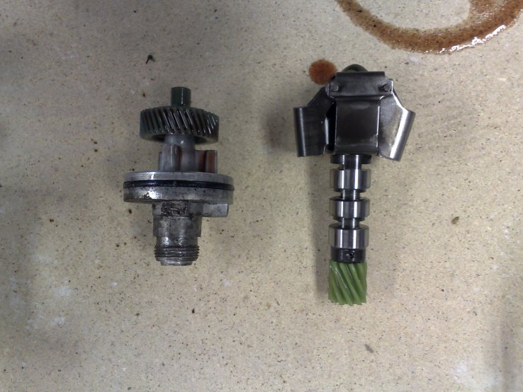
Governor cover, and Spedometer gear and Governor assembly in the right picture.
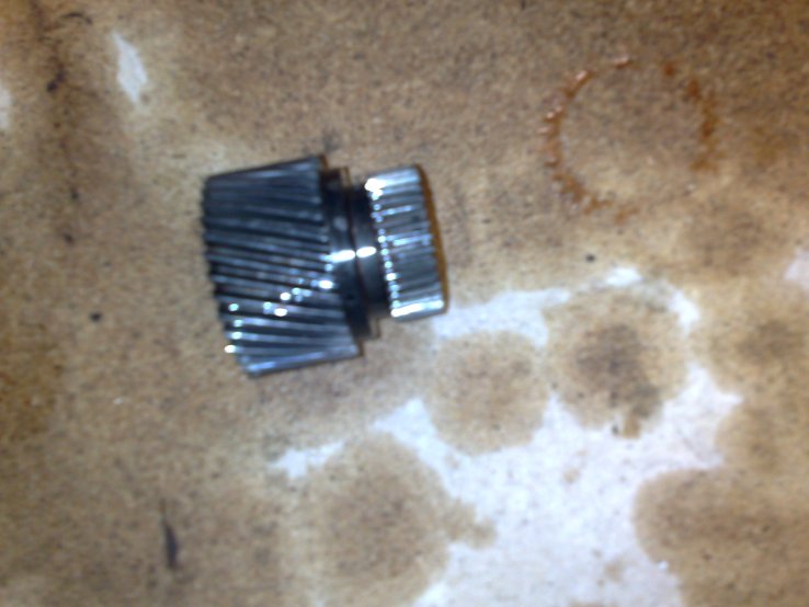
Next to come off is the tail housing. Remove the four bolts and pull it off. Now you see the tail shaft, and on it
is the speedo drive gear. Depress the clip holding it, and gently tap the gear back, off of the shaft.
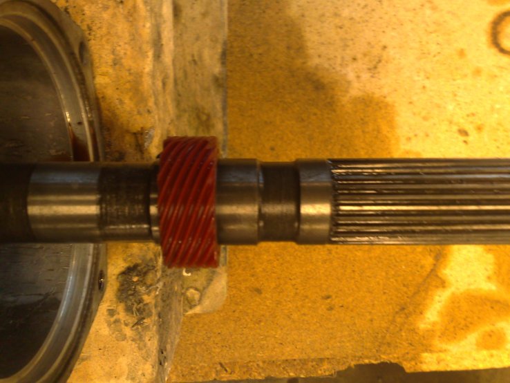
Tail cover and speedometer drive gear on tail shaft.
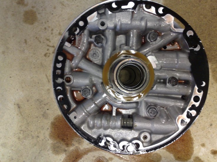
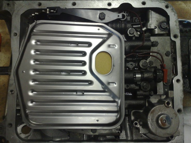
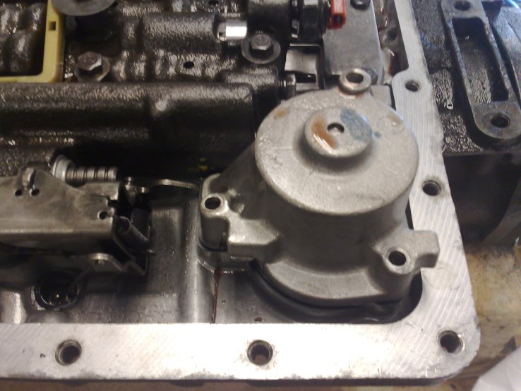
Now it is time to pull the pan and filter. Clean properly before removing the pan bolts. When the oil pan is removed
you'll be looking at something that looks like this:
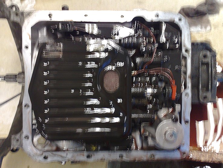
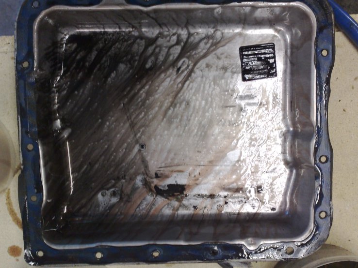
Tranny belly up showing filter, and inside of oil pan.
Pull off the filter and be sure to remove the filter seal that probably is stuck in the transmission housing.
Now you are looking at the brain of the transmission. This far has been a walk in the park compared to what will
come when we take the valve housing apart.
Remove the wiring for the TCC solenoid and the solenoid.
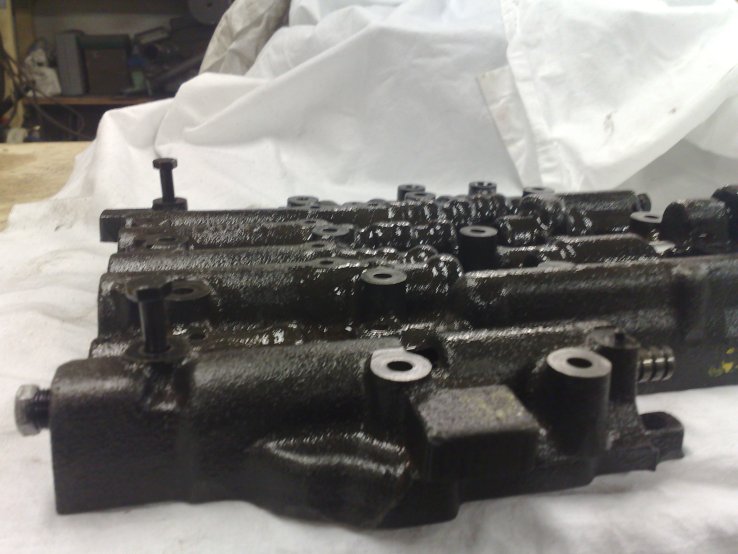
The valve body and solenoid looks like this:
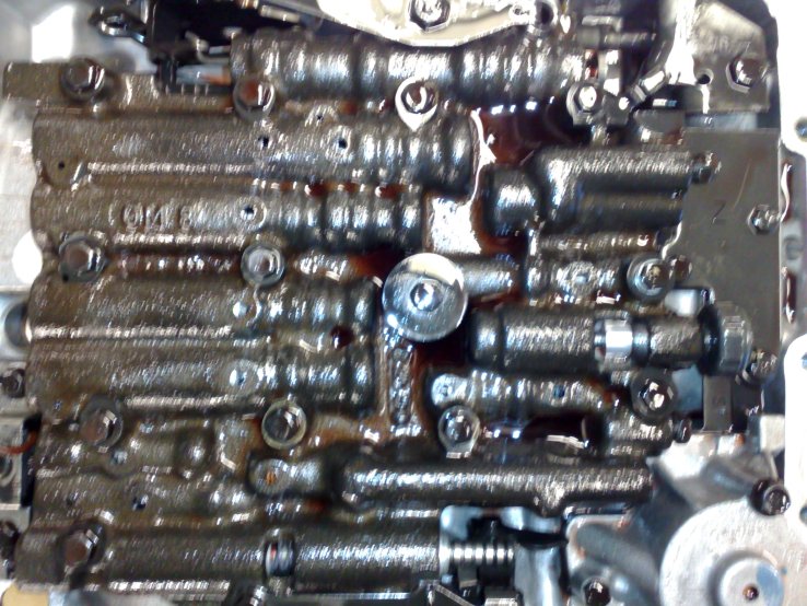
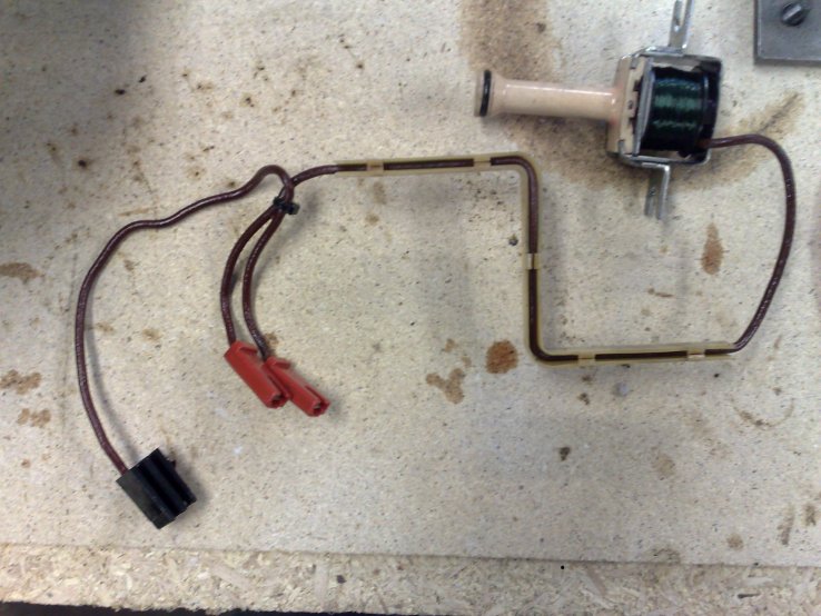
Valve body when filter is removed, and the solenoid set up.
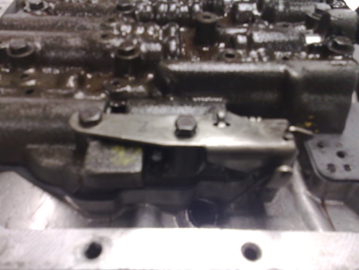
But before start on the valve body there are a few other items to remove, like the spring loaded roller for the
manual detent lever, the 1-2 accumulator, and the TV mechanism. In that order.
The manual detent roller and spring is simply just removed by taking out the bolt that holds it. The upper part of
the 1-2 accumulator is removed by undoing three bolts and then lift it up. It contains a piston, a pin, and spring.
By the way, this spring was broken clean off in my transmission.
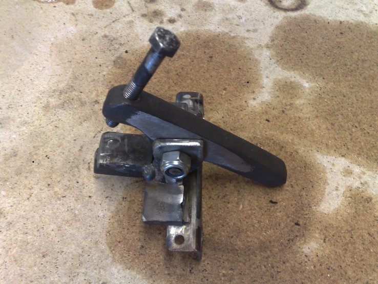
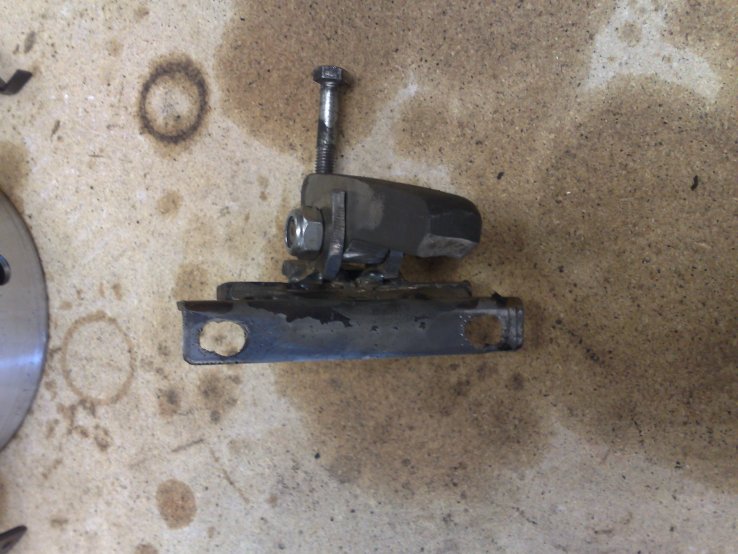
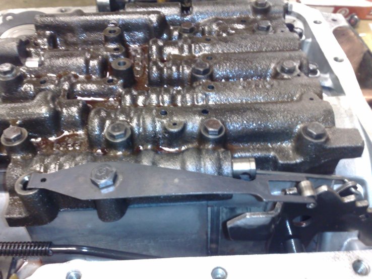
The TV mechanism is removed by taking out the two bolts holding it, and then dismount the lever from the TV cable.
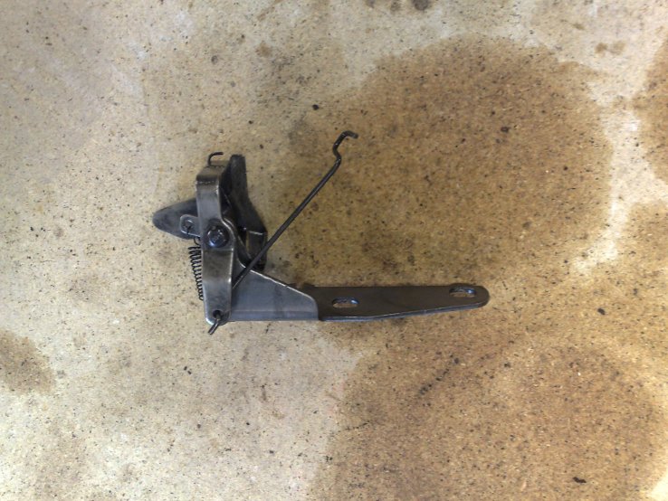
Manual detent spring roller and TV mechanism.
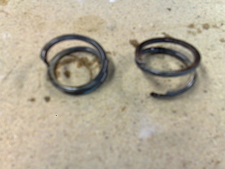
1-2 Accumulator cover, broken 1-2 accumulator spring.
If you're doing this for the first time, now is the time to get nervous... Time to attack the valve body. Loosen it
by removing the rest of the valve body bolts, carefully not to move it around. Grab the valve body and lift it up,
at least an inch, to clear the check balls that lie on the spacer plate beneath the valve body. Then turn the valve
body to dislodge the manual detent link. Place the valve body on a clean rag, safely away.
See... This was not that bad, was it?
Now you should see the spacer plate with a number of check balls. I my case there is three of them, but this can
vary between different years of transmissions. Carefully note the location of those check balls. If you don't get
them in the right place again you tranny won't work.
Now remove the cover plate just above the 1-2 accumulator, newer transmissions have a aux accumulator here and if
so, remove the aux accumulator tube first and then the aux accumulator. Mine was old enough to not have this.
When this is done you can, carefully, lift off the spacer plate with check balls in place, and put it away safely.
At this moment it's a good move to remove the 3-4 accumulator, as it now is uncovered when the spacer plate is
gone. It consists of one pin, one piston, and one spring. Just pull them out and tuck away safely.
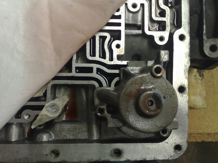
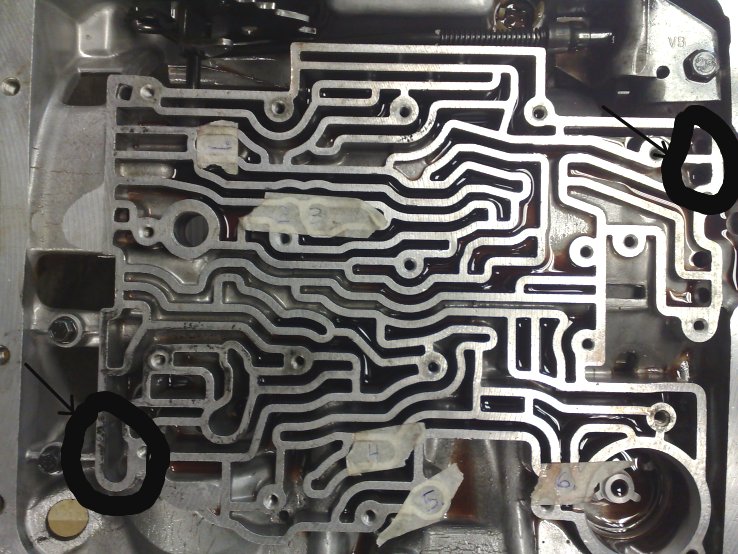
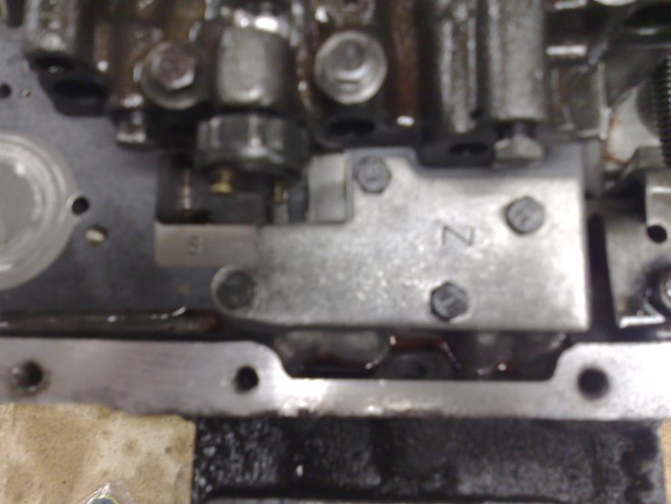
Now you're facing the lower part of the valve body. Guess what... More check balls!
I cleaned the surface of the valve body and took the check balls out one by one, and wrote numbers on tape and
stuck the tape bits over where the check balls should go. Better safe than sorry, as my repair manual was for the
newer model transmission, and the check ball placement was not the same.
The spacer plate and the lower valve body should look like this:
![]()

Spacer plate and lower valve body, with check balls.
With all check balls removed and properly stored we're moving on with the dismantling.
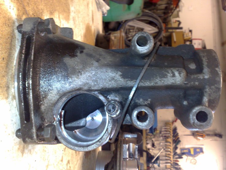
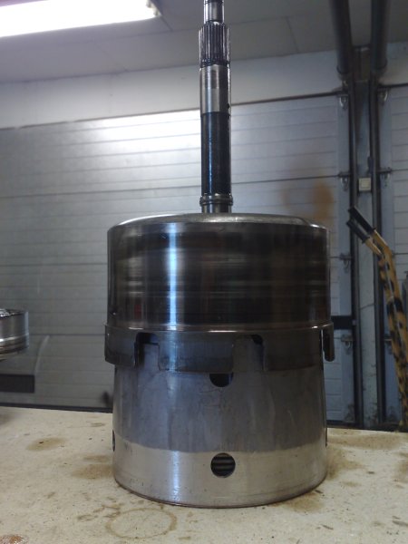
So, it's time to place the transmission upright, bellhousing facing up. To do this you need a hole for the tail
shaft in your work bench. That is, if you don't have the GM transmission fixture. I don't, so I cut a 2 1/2 inch
hole in the work bench.
Place something under the hole that can catch the tail shaft when it comes loose later in the dismantling process.
Might look something like this:
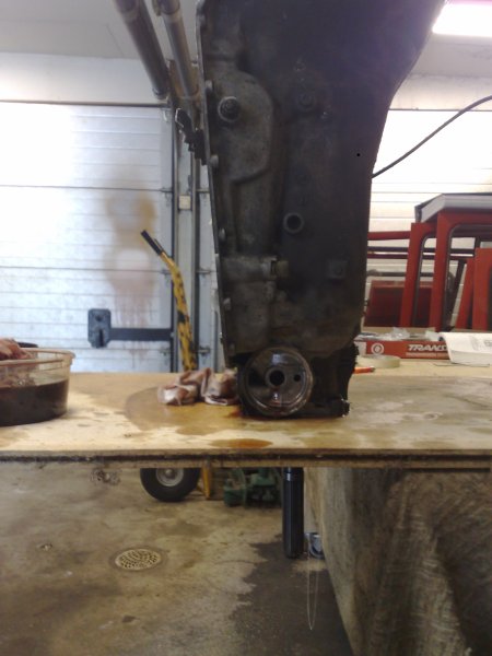
Transmission standing with tail shaft through hole in work bench.
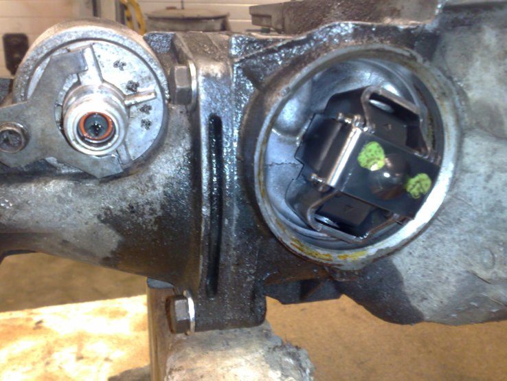
Time for some oil pump removal. With the tranny standing up, remove all bolts holding the pump assembly. Then use
either a special pump puller if you got one, or a regular puller to pull the pump assembly. I used a regular puller
and the trick here is to keep the jaws tightly quenched in the groove located behind the splines on the outer shaft.
The puller will push against the feed hole for the TCC in the inner shaft, so take it easy and don't force it. Just
ease the pump assembly out, then lift it off the inner shaft.

Pump assembly, front and rear side.
While we're at it, let's have some weight lifting exercises too... The next thing we lift out is pretty heavy so be
ready for it. Grab the input shaft and lift out the complete assembly, carefully negotiating the band that runs
around the drum that is coming out also. Take a break after this heavy lifting, and meanwhile remove the band and
the pin that holds the band. This pin is easily lifted out from the valve body. See following pictures.

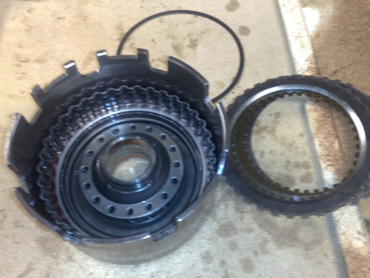
Input clutch and band.
What you see in the left of the above pictures is the input clutch and the reverse input clutch. The reverse clutch
is sitting on top of the input clutch, with the input shaft running through it.
Lift off the reverse cluch and set it aside for later adventures...
Band retractor pin and pin location in valve body.
Now when you look down into the transmission you should see something like in the picture below. Reach in and lift
out the input sun gear pictured below.
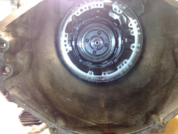
View down the transmission and input sun gear.
Now it's time for one of the more tormenting tasks. Pulling the tail shaft. You did remember to put something under
it, did you? Well, if not then now is the time. Also, wedge something under it to push it up as far as it goes, as
that will help getting the lock ring off.
The lock ring is as far down as you can come on the shaft, inside the planetary gear so it's a bit crowded there. A
pair of good quality lock ring pliers is needed for this task. The cheaper ones are too bulky to get down there...
When the ring is off, slide the tail shaft out from the back of the transmission and put it aside.

Tail shaft with lock ring loosely on it.
Now you can lift out the 3-4 clutch and put it on the table. Lift off the planetary gear and sprag, and you'll be
set up dismantle and it and put new frictions and steeles in.
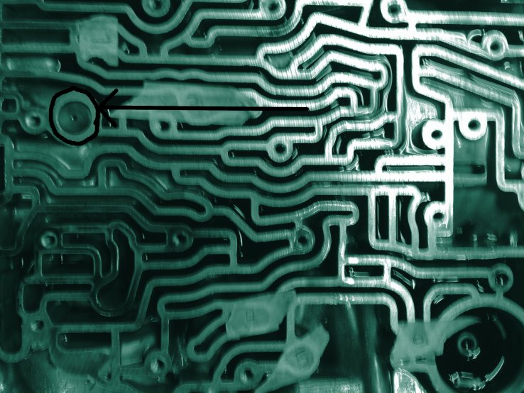
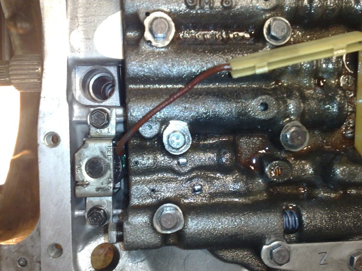
Now on to get the lo and reverse clutch out. If you look down the case you'll spot a large lock ring that locks
into the case. Take your favorite screwdriver and remove it. If you try to lift out the assembly now you'll notice
it won't work.
There is this little retainer spring that keeps it from coming loose, located down side of the transmission, a
little to the right. One leg of it is a little higher, you cant miss it, black as it is amongst all the aluminum.
Press it down and to the left, and presto, you'll be able to lift out the lo and reverse clutch and put it on the table.
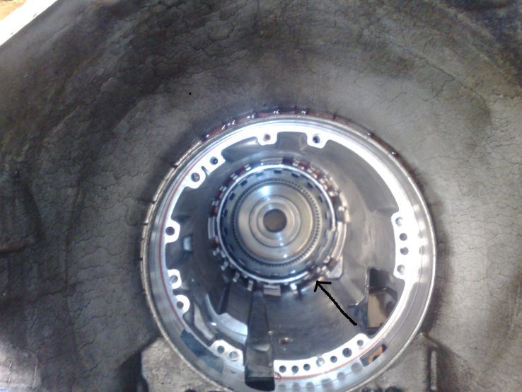
Case picture, retainer marked with arrow.
Oh, keep track of all the thrust washers and thrust bearings. There are a couple of them and you don't want to find
one left on the table when you're finished reassembling the transmission...
Oh, and keep things clean. Did I mention this before?
So, at this point we start to do the more rewarding stuff, like ripping everything apart and put in new frictions
and steels. Let's start with the lo and reverse assembly that you took out last.
Use your favorite screwdriver to remove the lock rings and lift out the stacks of steeles and frictions. Replace
with new ones from the Master Overhaul Kit. You did buy one of those, didn't you?
Clutch and clutch pack.
Do this for all cluch packs, and if you feel like getting a tighter and firmer slushbox you could always stack the
clutch packs with an extra steel plate, and if there's room and you got a good friction plate you could tuck one of
those in there too. I did it, let's see how that works out. Your milage may vary...
Be careful when you take the clutch packs out and duly note where and how it is assembled. There are some steel
plates that are reused. They're pretty easy to recognize as they're thicker than the ones that go between friction
plates. Make sure to line up all the teeth on the friction plates or you'll never be able to assembled it again.
Now you just drop all the clutches and other stuff back into the transmission case in the reverse order of that they
were removed in. It takes some wiggeling to get them together and the better you lined up the friction plate teeth,
the less amount of wiggeling it takes.
Put the reverse clutch over the input clutch (it really is the forward and overrun clutch, to be completly correct)
and install it as a unit, just as it came off.
When you installed the input and reverse clutch, take breath and check that the reverse clutch is located slightly
below the face for the oil pump. You can see it quite clearly through the slot from the valve body.
If it's not below the pump face you've done something wrong. Probably it is some friction plates that are not lined
up properly. Just pull it apart again and inspect, and correct the error.
Now install the 2-4 band. You'll have to push the reverse clutch towards the top of the transmission and sqeeze the
hooks of the band into place. Align the band retainer pin socket with the hole in the valve body and insert the pin.
Time to install the pump housing. Before installation, swap the pump filter for a new one. It's a dime sized plastic
thingie pushed into the side of the pump. Just pull it out and push in the new one. Put on a new seal on the pump,
and a new gasket on the pump face in transmission case. Slide the pump over the input shaft, observe pump orientation
as it only mounts in the correct position.
Let it slide into the case and push it into place by using two of the mounting bolts while rotating the input shaft.
If the shaft does not turn something is wrong. When the pump has bottomed out, mount the rest of the bolts.
Now it's time for the transmission to go belly up again. That is, we're going to put it with the valve body up to
reassemble the valve body with all them check balls and stuff.
Make sure everything is nice and clean, place the check balls into the lower valve body. You did note where they
should go, did you? If not you might be screwed...
Also, now is the time to change out the two small screens that are in the valve body. These are located one at the
front of the valve body, and one at the back of the valve body, pointing down inwards the transmission. See pictures
below.
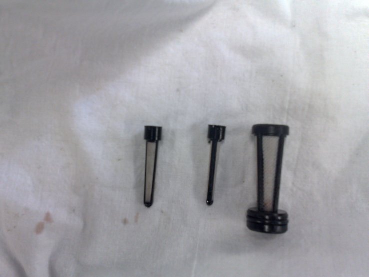
Screen locations and to the right the screens. The larger one is for the fluid pump.
Match up the lower gasket with the old one. There are gaskets for more than one transmission variation in the kit, so
be sure to pick the right one. Put it onto the lower valve body. Now put the 3-4 accumulator pin, piston, and spring
into the accumulator housing. This is the parts that go into the accumulator housing beneath the spacer plate.
![]()
Lower valve body with check ball positions and spacer plate with gaskets matched up.
In the pictures above the lower valve body with check ball positions, and in the second picture you see the spacer
plate and gaskets in place. You didn't forget the 3-4 accumulator, did you?
Now place the upper level check balls on the spacer plate and you're ready to install the upper valve body. Use one
or two valve body bolts as a guide for where to put it down. See picture below.

The upper level check balls, and the upper valve body with guide bolts.
Grab the upper valve body in a way that makes it possible for you to slip the manual detent link from the valve body
onto the manual detent lever. You'll probably have to turn the valve body about 90 degrees from its final position
and wiggle a bit to get it done. Carefully, not to disturb the upper check balls! Keep the valve body about an inch
above the spacer plate and you'll be good.
Set down the valve body usint the bolts as a guide for placement. Put in a couple of more bolts and tighten it loosely.
Now wipe the sweat off of your forehead, you've done the worst part of the job. From here it's mostly gravey and
bisquits. Put back the manual detent lever spring and roller thingie, and the TV mechanism as per pictures below.
On the TV mechanism there's a thin pin that goes into a hole that has a ball in it. This pin is a emergency thingie
that assures the transmission to work even if the TV cable breaks or is unhooked.
Manual detent lever spring and TV cable mechanism.
Now put the cover back right above the 1-2 accumulator, the one with four short bolts, shown below. Then install the
solenoid assembly, and the last upper valve body bolts. Pictures below.
Cover plate and solenoid assembly.
Almost finished with the guts of the tranny now. Install the 1-2 accumulator piston and pin in the accumulator
housing, insert the spring, and then install the 1-2 accumulator assembly. If you haven't tightend the valve body
bolts yet, now is the time to do it. The manual calls for 11Nm torque. Now install the fluid filter with a new seal.
Filter and 1-2 accumulator installed.
Now install the gasket, and pan.
Before installing the pan, it really is a good idea to put a drain plug in the pan. This eliminates the event of
getting 5 quarts of hot transmission fluid all over you when changing fluid and filter in the future.
I just drilled a hole in the pan, passenger side, rear of pan, and welded a nut on the out side. A bolt and copper
washer makes it complete.

Drain plug welded to pan.
Put the the speedometer drive gear back on the tail shaft, that is if you took it off in the first place... Then put
the tail cover back on the transmission. Mount the speedometer driven gear assembly and the governor assembly and
governor cover. The cover should fit tightly so the use of a hammer and punch on the outer edge is the way to go.
Pictures below...

Tail cover, speedo assembly and governor assembly (before cover is in place).
Now flip the transmission on its side and install the servo and servo cover. Put it in piece by piece, and last
secure the cover with the lock ring. You need the same tool to install it as you used to remove it.
So, now you're done. Wasn't really that bad, was it?
Now install the converter, install the transmission, and fill her up. First fill 5 quarts, then start engine, then
fill five more quarts. Test drive until fluid is hot, then top off until dipstick says full. Use Dexron II or III.